
Multislice CTPrinciples and Perspectives
Mindy M. Horrow, MD, FACR
Director of Body Imaging
Albert Einstein Medical Center
All photos retain the copyrights of their original owners
© Mindy Horrow, MD
Before CT
Entire areas of body inaccessible toradiography (brain, retroperitoneum,etc.)
Some useful diagnostic procedureswere either potentially harmful orconsiderably uncomfortable(exploratory laparotomy,pneumoencephalography)
Principles of CT
Radiographic tube emits x-rays whilerotating axially around patient
Array of detectors on opposite side ofpatient detects x-rays transmittedthrough patient
Computer algorithms use digitized datafrom detectors to create axialtomographic images of body.
CT = tomography + algorithms + highspeed digital computers
Tomography- CT actually eliminatesunwanted material, outside of scan planeinstead of just blurring it (1921-conventional tomography)
Reconstruction algorithms- Fast FourierTransformation: allows mapping offunction of space into a function offrequency using the theorem that anyfunction can be decoded into a sum ofsine and cosine functions (described byFourier in 1811)
Principles of CT
Development of Workable CTScanner
1963- Cormack in S. Africa developsalgorithm for accurate reconstruction ofimages from radiographic projections
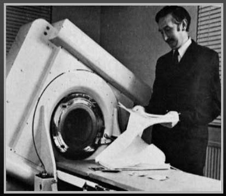
1971- Hounsfield, a computer engineer inEngland produces first working CTscanner used clinically on patients.Produced 70 head CTs in 6 mos, at 4 minper slice, recorded on magnetic tape withtwo days reconstruction time per case.
Cormack and Hounsfield awarded NobelPrize in medicine and physiology in 1979
Sir Godfrey Hounsfield with aprototype CT scanner in 1974
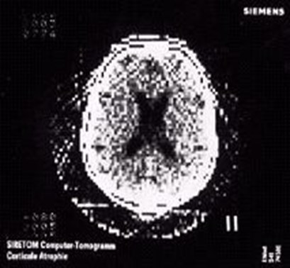
Head CT circa 1975 with 128 x 128 matrix
Radiology: Volume 119, 1976
Davis, Taveras, New, et al. Diagnosis of EpidermoidTumor by Computed Tomography
Hahn, et al The Normal Range and position of the PinealGland on Computed Tomography
Huckman, Ramsey, et al. Computed Tomography in theDiagnosis of Pseudotumor Cerebri
Messina, Potts, et al. Computed Tomography: Evaluationof the Posterior Third Ventricle
O’Connor, et al. Computed Tomography in a CommunityHospital
Sagel, Stanley, Evens. Early Clinical Experience withMotionless Whole Body Computed Tomography
Sagel, Stanley, Levitt, et al.Computed Tomography of theKidney Radiology 124:359-370, 1977
“Computed tomography is an extremelyaccurate method of obtaining more definitivediagnostic information about a renal massdiscovered on a urogram. Benign renal cystsare readily distinguished from solid renalneoplasms, and CT is often valuable incharacterizing possible juxtarenal masses.The cause of a nonfunctioning kidney(s) on aurogram can often be discerned, andhydronephrosis is easily detected.”
Proliferation of CT
By 1976, 3 years after Hounsfield’spublications, 22 companies weremanufacturing CT scanners
By 1979 1000 scanners were operating in50 countries
Competition produced rapidtechnological sophistication
Introduction of fan beam-scanningdecreased scan time from 300 sec to 2sec per slice in 4 years
Conventional CT scanners
Employ fan of x-ray beams and a largedetector array
3 types of gantries: translate-rotate,rotate-rotate, rotate-stationary
Involves alternating patient translationand x-ray exposure
Each rotation of x-ray tube generates datafrom which a corresponding axial imageis reconstructed
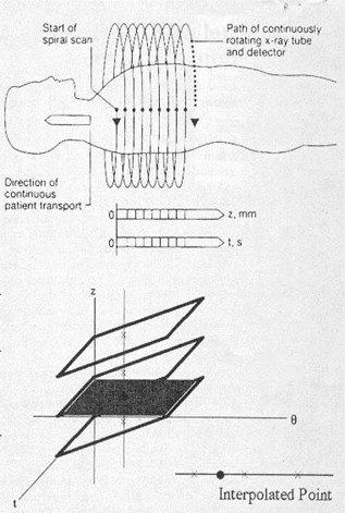
Helical (spiral) CT
Simultaneous patient translation and x-rayscanning generates volume of data
X-ray beam traces a helix of raw data fromwhich axial images must be generated
Each rotation generates data specific to anangled plane of section
To create true axial image, data points aboveand below desired section must beinterpolated to estimate value in axial plane
Thus, interval between reconstructedtranssexual images can be chosenretrospectively
Technological considerations ofhelical CT
Slip-ring technology (no electrical cablesconnecting gantry to ground) allowssource detector assembly to rotatecontinuously. Previously, frequent,abrupt changes between scans werenecessary to permit winding andunwinding of cables
More robust x-ray tubes and generatorswere developed to allow high tube currentfor prolonged duration. Also needed tobe lightweight enough to be mounted inslip ring gantry
Comparison of single slice andmulti-slice CT
Detector configuration
Reconstructions
Detector design
Definition of pitch
Pitch and image quality
Spatial resolution
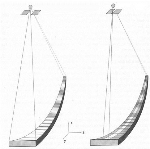
Configuration of detectors
SS- long, narrow array with lengthof single detector aligned in z axis
MS- detector array segmented in zaxis, a mosaic
–Allows for simultaneous acquisition ofmultiple images in scan plane withONE rotation
Mosaic Detector
•16 cells in Z direction
--each cell 1.25 mm (in Z)
•16 cells (Z) x 912 cells (transverse) = 14592 total cells
•Signal collected from 4 channels/2 flex connectors
DiodeDiode
FET Switching ArrayFET Switching Array
Reconstructions
SS- reconstruct images of SAMEthickness with different image indexing(table increment intervals)
MS- acquire 3D raw data that arecontiguous in space. Therefore canreconstruct images at variousthicknesses AND at different intervals
–If image index < image thickness, results inoverlapping slices
–Must have raw data available for any type ofreconstruction
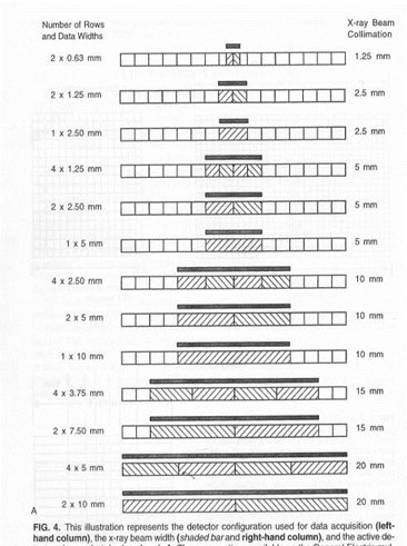
Multi-slice detector design(GE 4 slice scanner)
16 equal elements in z axis, 20mmmaximum collimator width *
Can acquire 1, 2, or 4 images per rotation
For example: with collimator at 10mm canmake 4 images @ 2.5mm, 2 images @5mm or 1 image @ 10mm
Thinnest slice thickness that can bereconstructed depends entirely oncombination of slice thickness and tablespeed
* A single 1.25 detector is made of two .63 detectors
Axial Configurations4 x 2.5 mm
DiodeDiode
FET Switching ArrayFET Switching Array
4 signals collected from eight 1.25 mm detectors with 2 detectors contributing to each signal
2.5 mm is the minimum slice thickness because two 1.25 mm detectors are combined per signal
Cells can be combined to form 4 slices @ 2.5 mm each or 2 slices @ 5 mm each or 1 slice @ 10 mm
1
2
3
4
1
2
1
4i mode = each set of
2 cells becomes a slice
@ 2.5 mm each
1i mode = 4 sets
(of 2 cells each) are
combined to form
1 slice @ 10 mm
2i mode = 2 sets
(of 2 cells each) are
combined to form
2 slices @ 5 mm each
Pitch
SS = table travel per rotation
image thickness
If table travel > slice thickness, pitch > 1
MS = table travel per rotation
total active detector width*
* = x-ray beam collimation
Table travel/ rotation =7.5mm
Image thickness = 5mm
Pitch = 7.5 = 1.5
5.0
Table travel/ rotation =7.5mm
Four Images with
thickness = 2.5mm
Pitch = 7.5 = .75
(4 x 2.5)
SS MS
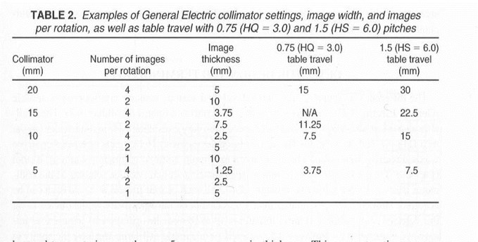
GE Definition of Pitch
Table travel per rotation = 7.5 = 3single image slice thickness 2.5
(High quality mode)
i.e.. When 4 images are acquired per tuberotation, associated table travel is 3times image width
GE Definition of Pitch
Table travel per rotation = 15 = 6single image slice thickness 2.5
(High speed mode)
i.e.. When 4 images are acquired per tuberotation, associated table travel is 6times image width
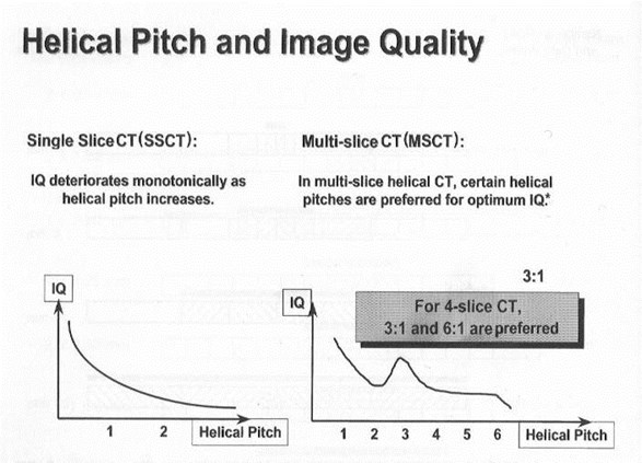
Pitch and Image Quality
SS- Image quality decreases aspitch increases
MS- GE scanners have uniqueproperty of forming images withparticularly good quality at 2specific pitch values, HQ and HS
Pitch and Noise
To reconstruct image, projections must becollected over 180 gantry rotation and fan angle ofx-ray beam (45 ), about 2/3 of spiral
Since reconstruction algorithms need fixednumber of projections to make image and sincepitch only affects how these projections aredistributed in spiral, not the number of projections,pitch does not affect noise
No difference between SS and MS
Image Quality: ContrastResolution
Ability of imaging system to detect asingle structure that varies only slightlyfrom its surroundings
Related to noise AND pitch
–Less noise, fewer distractions, increasedability to perceive low density object
–Contrast resolution in x-y plane as pitch for SSCT but does NOT change for MSCT
Contrast Resolution
SS- pitch causes broadening of slice-sensitivity profile. Scanner needs to haveenough projections to reconstruct sliceand is forced to seek them outside ofspecific z axis. Some projections maynot pass through object in question andresults in “under-sampling” which blursobject
Contrast Resolution
MS- pitch does not broaden SSPbecause at least one of multiple rows ofdetectors passes into x-y planecontaining object in question. Becauseof multiple detectors, highly unlikely thatprojections distant from imaging planewill be needed.
Z axis resolution Dose
SS- increasedpitch decreases zaxis resolution
MS- increasedpitch has littleeffect on z axisresolution
SS- increasedpitch decreasesradiation dose
MS increasedpitch, machinecompensates withincreased mA anddose does notchange
Dose-Pitch Relationship
For SS, if pitch>1, dose decreases
pitch<1, dose increases
For MS, if pitch>1, dose similar
pitch<1, dose similar
When pitch is<1 in MSCT, images areinterleaved, with reconstructed slicesusing information from surrounding slices,allowing a decrease in technical factors
Reconstruction Algorithms
SS and MS are similar
First step done by machine, z axisinterpolator works on raw data to weightprojections nearest the slice locationmost heavily
Second step selected by user: for softtissue images, want to suppress noiseand increase low contrast sensitivity. Forbone want higher contrast.
Protocols for MSCT
Image thickness, detector configuration,collimation, table speed, interval,reconstruction algorithms
IV contrast parameters
Length of acquisition
Technique: kV, mA, sec
Reconstruction algorithm
FOV- for scan, for display
Problems/Pitfalls inProtocol Design
Timing of bolus and data acquisition
Preset filming
“Pseudo-enhancement”
Venous artifacts
Increasing numbers of tiny lesions
Timing
Routine chest protocol with 20 cmcoverage, table speed 11.25mm/rotation, takes 14 sec for entirescan at 0.8 sec/slice
Using 40 sec prep delay
–If injection rate is 2cc/sec, use 108 cc
–If injection rate is 2.5, use 128 cc
Filming
Because of high levels of vascularenhancement, classic soft tissuewindows will not be appropriatefor all organs. Lesions may beobscured in organs that enhancebrightly such as kidney andarteries (pulmonary emboli,dissection flaps)
Other issues
“Pseudo-enhancement” of renal cystssurrounded by parenchyma becomes agreater problem because of higher levelsof renal enhancement
Increasing numbers of tiny lesions inlung, liver, etc. Are these metastases?
Venous artifacts, which simulatethrombus become more obvious andfrequent
Can I reconstruct thinner slicesthan those printed on image?
PE protocol 2.50mm/7.50 1.5:1
–Image 2.5mm thickness
–Table speed = 7.5 mm/rotation
–Pitch = 1.5:1 (HS mode)
7.5 1.5 = 5mm collimation
With 4 slices per rotation, detector size mustbe 1.25mm and therefore this is thinnest slicethickness that one can reconstruct
16 slice scanner
Routinely 360º rotation in 0.5 sec (798 data points)
Can go to 0.4 sec rotation for cardiac scanning
For larger patients, increase rotation time
Using the “large-large” FOV, each pixel is 1mm inx-y plane. Thus each vowel is 1 x1 x1mm =ISOTROPIC SCANNING
Can also achieve isotropic scanning with smallFOV (head, neck, extremity) in which each voxel is0.5mm
16 slice scanner
Helical pitch = table distance perrotation / slice thickness
–15mm / 1mm = 15
Beam pitch = helical pitch / imagethickness
–15 / 16 = 0.938
16 slice scanner
Prospective Gating: 0.4 sec gantry speed.Machine counts 5 cycles, calculates R-Rinterval, takes 0.25 sec scan, ending priorto beginning of next R wave. Requiresheart rate < 80 bpm. Table moves duringnext R-R interval. Each scan covers 4images @ 3mm thickness.
Retrospective gating = gatedreconstruction. Helical acquisition withECG over raw data. When ECG is at a givenpoint, take data at that time to make image.
MSCT
Examples of UniqueProtocols
Lung
“Abnormal CXR”- survey exam with 5mmsections, but choose detector set of 4 1.25mmso that retrospective thin slices through asmall nodule can be obtained without re-imaging
Airway disease- single breath hold with 1 or1.25mm collimation. Evaluate trachea withoverlapping 3-5mm sections, use 1mmsections to assess small airways. Combineinspiratory & expiratory views for physiologicevaluation, air trapping
PE- 1.25- 2.5mm, HS mode scan averagethorax in 10-12 sec. Use bolus tracking.Helpful to view as reconstructions.
Abdomen
Porta hepatis- because of complicatedanatomy & oblique orientation, 3mmsections recon w 50% overlap curvedor coronal reformats
Liver and pancreas- multiple phases insingle breath holds
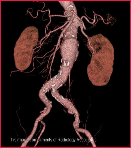
Kidneys- 3D reconstructions similar toIVU and angiography
Musculoskeletal System
0.5mm slice thickness can result inisotropic data set such that x-, y- and z-axes are equal in size (Will be standardon 8 and 16 slice scanners)
Trauma- if scanning chest, abdomen,pelvis can change FOV, recon to thinnerslices, change to bone algorithm and do2D and 3D recons to review spine,without re-imaging as spine protocol
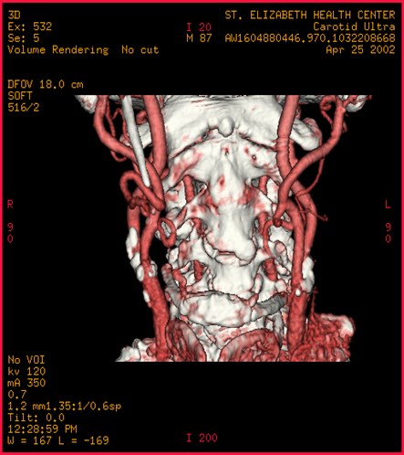
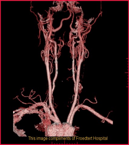
Head and Neck
Elimination of direct coronal imaging
Reformats can avoid artifacts from teeth
3D displays for trauma and congenitalanomalies
3D reformats can provide endoscopicviews of larynx, hypopharynx and tocalculate tumor volumes
Angiographic and perfusion studies
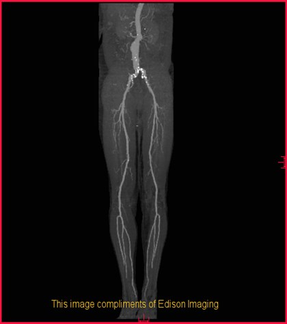
Post Processing Applications
Huge numbers of images can be generatedfrom original data set and reformatted indifferent planes, surface displays,angiographic techniques, virtual endoscopy
Issues of how to view and store images
QUIZ
1. For SSCT with image thicknessof 2.5 mm and table speed of 4.0mm/rotation, the pitch =__________
2. For MSCT with tech requesting 4slices with 3.75 mm thickness andtable speed of 11.25 mm/rotation,pitch = ________________
a. SSCTb. MSCTc. bothd. neither
3. Re-indexing, or creating overlapping slices ispossible on
4. Reconstruction images to different slicethicknesses is possible on
5. X-Y axis resolution (image quality) does notchange significantly with higher pitch on
a. SSCTb. MSCTc. bothd. neither
6. Noise increases with increasing pitch on
7. As pitch increases, > 1, the radiation dose tothe patient decreases on
8. The reconstruction algorithm involves 2steps, the z axis interpolator and application ofspecific algorithms such as smooth, standard,bone, etc on
1. For SSCT with image thickness of 2.5mm and table speed of 4.0 mm/rotation,the pitch = 1.6
2. For MSCT with tech requesting 4slices with 3.75 mm thickness and tablespeed of 11.25 mm/rotation, pitch = 0.75
a. SSCTb. MSCTc. bothd. neither
3. Re-indexing, or creating overlapping slices ispossible on c
4. Reconstruction images to different slicethicknesses is possible on b
5. X-Y axis resolution (image quality) does notchange significantly with higher pitch on b
a. SSCTb. MSCTc. bothd. neither
6. Noise increases with increasing pitch on d
7. As pitch increases, > 1, the radiation dose tothe patient decreases on a
8. The reconstruction algorithm involves 2steps, the z axis interpolator and application ofspecific algorithms such as smooth, standard,bone, etc on c
References
Brink JA, Heiken JP, et al. Helical CT:Principles and TechnicalConsiderations. Radiographics 1994;14:887-893
Friedland GW and Thurber BD. The Birthof CT. AJR; 167: 1365-1370
Silverman PM. multi-slice ComputedTomography- A Practical Approach toClinical Protocols. Lippincott Williams &Wilkins, 2002; Chapter 1: 1-29
Thanks to GE for providing images
The End